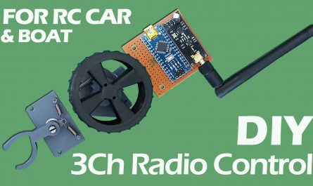
Some model airplanes have delta wings. Some have V-tails. In delta wing models, two channels must work together as both aileron and elevator. In V-Tail models, it must work both elevator and rudder. This receiver has the necessary mixing feature.
Download Receiver Code, PDF and Gerber Files: https://drive.google.com/file/d/1BHzEPPrXesnFIR55zIHX7_UMv9p4uMUp/view?usp=sharing


Needs:
GT-24 NRF24L01+PA+SMD: https://s.click.aliexpress.com/e/_DekKUm9 OR https://s.click.aliexpress.com/e/_oEjrKrK
Arduino Micro Pro: https://s.click.aliexpress.com/e/_oEww0wy
100uF (16V or 25V) electrolytic capacitors : https://s.click.aliexpress.com/e/_DBJpcn1
10uF electrolytic capacitors : https://s.click.aliexpress.com/e/_DDVm071
100nF (104) ceramic capacitor: https://s.click.aliexpress.com/e/_DmUGp7T
Female Header Pin (12 pins) 12P Female: https://s.click.aliexpress.com/e/_DDqmgbh
Copper Clad Board: https://s.click.aliexpress.com/e/_oDTDgMM
LM1117 3.3V Regulator IC: https://s.click.aliexpress.com/e/_oFQSuhw OR https://s.click.aliexpress.com/e/_ooUqa3e
2×4 pin Header: https://s.click.aliexpress.com/e/_DdnClhn
Optional:
80W Soldering Iron: https://s.click.aliexpress.com/e/_oFNZ4UY
A4 Transfer Paper (Toner): https://s.click.aliexpress.com/e/_oFMhbda
Receiver Code For Arduino Micro Pro:
#include <SPI.h>
#include <nRF24L01.h>
#include <RF24.h>
#include <Servo.h>

int ch_width_1 = 0;
int ch_width_2 = 0;
int ch_width_3 = 0;
int ch_width_4 = 0;
int ch_width_5 = 0;
int ch_width_6 = 0;

Servo ch1;
Servo ch2;
Servo ch3;
Servo ch4;
Servo ch5;
Servo ch6;

struct Signal {
  byte throttle;
  byte pitch;
  byte roll;
  byte yaw;
  byte aux1;
  byte aux2;
};

Signal data;

const uint64_t pipeIn = 0xABCDABCD71LL;
RF24 radio(8, 10);

void ResetData() {
  data.throttle = 0;
  data.roll = 127;
  data.pitch = 127;
  data.yaw = 127;
  data.aux1 = 0;
  data.aux2 = 0;
}

void setup() {
  ch1.attach(2);
  ch2.attach(3);
  ch3.attach(4);
  ch4.attach(5);
  ch5.attach(6);
  ch6.attach(7);

  ResetData();
  radio.begin();
  radio.openReadingPipe(1, pipeIn);
  radio.setChannel(100);
  radio.setAutoAck(false);
  radio.setDataRate(RF24_250KBPS);
  radio.setPALevel(RF24_PA_MAX);
  radio.startListening();
}

unsigned long lastRecvTime = 0;

void recvData() {
  while (radio.available()) {
    radio.read(&data, sizeof(Signal));
    lastRecvTime = millis();
  }
}

void loop() {
  recvData();
  unsigned long now = millis();
  if (now - lastRecvTime > 1000) {
    ResetData();
  }

  int pitchValue = map(data.pitch, 0, 255, -150, 150);
  int yawValue = map(data.yaw, 0, 255, -150, 150);

  int ch2Value = pitchValue - yawValue;
  int ch4Value = pitchValue + yawValue;

  ch_width_2 = map(ch2Value, -300, 300, 2000, 1000);
  ch_width_4 = map(ch4Value, -300, 300, 1000, 2000);

  ch_width_1 = map(data.roll, 0, 255, 1000, 2000);
  ch_width_3 = map(data.throttle, 0, 255, 1000, 2000);
  ch_width_5 = map(data.aux1, 0, 1, 1000, 2000);
  ch_width_6 = map(data.aux2, 0, 1, 1000, 2000);
  ch1.writeMicroseconds(ch_width_1);
  ch2.writeMicroseconds(ch_width_2);
  ch3.writeMicroseconds(ch_width_3);
  ch4.writeMicroseconds(ch_width_4);
  ch5.writeMicroseconds(ch_width_5);
  ch6.writeMicroseconds(ch_width_6);
}
Channels 2 and 4 are mix channels. Servos connected to these channels perform elevator and aileron functions for delta wing model aircraft. For V-Tail models, they perform elevator and rudder functions.
If one of the servos is not moving in the direction it should be; For example, when we pull the elevator arm, both servos should move in the upward direction. If one of them is moving in the opposite direction, change the 1000 and 2000 values in the relevant line.
Example:
ch_width_2 = map(ch2Value, -300, 300, 2000, 1000);
instead
ch_width_2 = map(ch2Value, -300, 300, 1000, 2000);
Analysis of the receiver code; (Which line does what?)
// 6-Channel Delta Mix & V-Tail mix Receiver (FOR ARDUINO MICRO PRO)

#include <SPI.h>          // Include SPI library for communication with the nRF24L01 module
#include <nRF24L01.h>     // Include nRF24L01 library for nRF24L01 module
#include <RF24.h>         // Include RF24 library for radio communication
#include <Servo.h>        // Include Servo library for controlling servos

// Variables to store the pulse width for each channel
int ch_width_1 = 0;
int ch_width_2 = 0;
int ch_width_3 = 0;
int ch_width_4 = 0;
int ch_width_5 = 0;
int ch_width_6 = 0;

// Servo objects for each channel
Servo ch1;
Servo ch2;
Servo ch3;
Servo ch4;
Servo ch5;
Servo ch6;

// Structure to store the received signal data
struct Signal {
  byte throttle;  // Throttle channel
  byte pitch;     // Pitch channel
  byte roll;      // Roll channel
  byte yaw;       // Yaw channel
  byte aux1;      // Auxiliary channel 1
  byte aux2;      // Auxiliary channel 2
};

Signal data;  // Create an instance of the Signal structure

// Define the radio communication pipe address
const uint64_t pipeIn = 0xABCDABCD71LL;

// Create an RF24 radio object with pins 8 (CE) and 10 (CSN)
RF24 radio(8, 10);

// Function to reset the signal data to default values
void ResetData() {
  data.throttle = 0;   // Set throttle to 0
  data.roll = 127;     // Set roll to neutral (127)
  data.pitch = 127;    // Set pitch to neutral (127)
  data.yaw = 127;      // Set yaw to neutral (127)
  data.aux1 = 0;       // Set auxiliary channel 1 to 0
  data.aux2 = 0;       // Set auxiliary channel 2 to 0
}

void setup() {
  // Attach servos to respective pins
  ch1.attach(2);
  ch2.attach(3);
  ch3.attach(4);
  ch4.attach(5);
  ch5.attach(6);
  ch6.attach(7);

  ResetData();  // Reset signal data to default

  // Initialize the radio module
  radio.begin();
  radio.openReadingPipe(1, pipeIn);  // Open the reading pipe
  radio.setChannel(100);             // Set the radio channel to 100
  radio.setAutoAck(false);           // Disable auto-acknowledgment
  radio.setDataRate(RF24_250KBPS);   // Set data rate to 250 kbps
  radio.setPALevel(RF24_PA_MAX);     // Set power amplifier level to maximum
  radio.startListening();            // Start listening for incoming data
}

unsigned long lastRecvTime = 0;  // Variable to store the last received data time

// Function to receive data from the radio module
void recvData() {
  while (radio.available()) {
    radio.read(&data, sizeof(Signal));  // Read the data into the Signal structure
    lastRecvTime = millis();            // Update the last received time
  }
}

void loop() {
  recvData();  // Receive data from the radio

  unsigned long now = millis();  // Get the current time
  if (now - lastRecvTime > 1000) {
    ResetData();  // If no data received for 1 second, reset the data
  }

  // V-tail mixing process | V-tail miksleme işlemi
  int pitchValue = map(data.pitch, 0, 255, -150, 150);  // Scale pitch value between -150 and 150
  int yawValue = map(data.yaw, 0, 255, -150, 150);      // Scale yaw value between -150 and 150

  // Mixed values for channels 2 and 4
  int ch2Value = pitchValue - yawValue;  // Channel 2: Pitch - Yaw
  int ch4Value = pitchValue + yawValue;  // Channel 4: Pitch + Yaw

  // Map the mixed values to servo pulse width (1000-2000 microseconds)
  ch_width_2 = map(ch2Value, -300, 300, 1000, 2000);  // Map ch2Value to pulse width
  ch_width_4 = map(ch4Value, -300, 300, 2000, 1000);  // Map ch4Value to pulse width (reversed direction)

  // Map other channels to servo pulse width
  ch_width_1 = map(data.roll, 0, 255, 1000, 2000);      // Roll channel
  ch_width_3 = map(data.throttle, 0, 255, 1000, 2000);  // Throttle channel
  ch_width_5 = map(data.aux1, 0, 1, 1000, 2000);        // Auxiliary channel 1
  ch_width_6 = map(data.aux2, 0, 1, 1000, 2000);        // Auxiliary channel 2

  // Send PWM signals to the servos
  ch1.writeMicroseconds(ch_width_1);
  ch2.writeMicroseconds(ch_width_2);
  ch3.writeMicroseconds(ch_width_3);
  ch4.writeMicroseconds(ch_width_4);
  ch5.writeMicroseconds(ch_width_5);
  ch6.writeMicroseconds(ch_width_6);
}
For the transmitter you can use the version I published before. It is compatible with this receiver.
How To Make 6-Channel (Optional 8 Channel) Radio Control. Range 2000m+
_______________________________________
GENERAL INFO:
Before uploading the codes to Arduino, you need to download the necessary library files to your computer.
If there are no library files, the installation will not occur and an error will occur.
Required library file:
SPI.h
nRF24L01.h
RF24.h
Servo.h
NRF24 Module Library File Links for download …..:
NRF24 Module library Files (Github page): https://github.com/nRF24/RF24
NRF24 Module library File (zip) : https://github.com/nRF24/RF24/archive/master.zip
Servo Library: https://www.arduinolibraries.info/libraries/servo
How to install Arduino IDE? & How to install Library File?