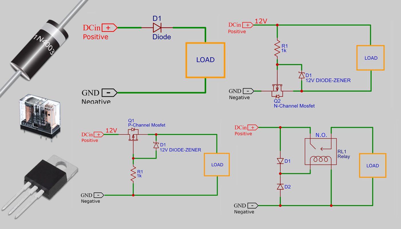
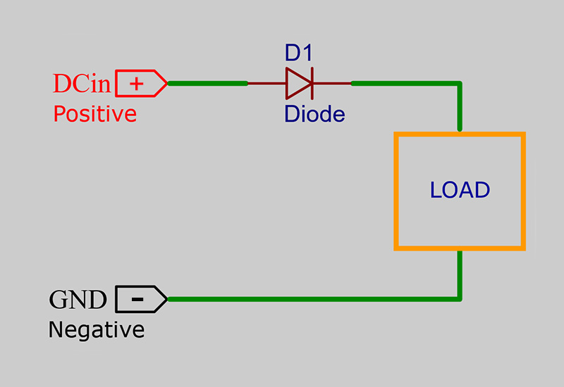
Series Diode Connection for Reverse Polarity Protection:
The series diode is the cheapest and simplest protection method. It is very easy to implement and can be
preferred for circuits that do not require high current. High current may cause the diode to overheat and fail. A
diode suitable for the maximum current required by the circuit should be chosen.
Another issue is the voltage drop.
For circuits powered by low voltage, the voltage drop caused by the diode can be problematic. Even at low
current, there is a voltage drop of about 650mV, and this loss increases as the current increases. In a 1A diode,
the loss is approximately 900mV, which creates a significant drop in the supply voltage of the circuit.
When a Schottky diode is used, the voltage drop decreases to about 200mV instead of 650mV. However, this
depends on the current; at maximum current, the voltage drop can be around 1V in a standard silicon diode and
around 500mV in a Schottky diode.
Schottky diodes offer better performance, but they are generally more expensive and not suitable for high
voltages.
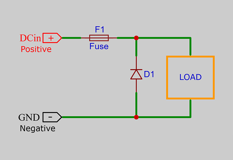
Protection with Parallel Diode and Fuse:
A parallel diode must support a higher current than the power supply can provide. The diode must be rated
accordingly.
Because if current exceeds its capacity, the diode will overheat and burn before the fuse can cut the circuit, and
the circuit will be exposed to reverse voltage.
When a properly rated diode is used, it will work as it should. If the power supply is reversed, the fuse will blow
and cut the circuit. However, the diode may also be damaged.
The negative aspects of this method are that repairs may be required to replace both the fuse and the diode. In
addition, in some cases, the time elapsed before the fuse blows may be sufficient to damage the circuit.
For this reason, fast fuses should be preferred. The maximum operating current of the circuit should be taken into
account for the rating of the fuse.
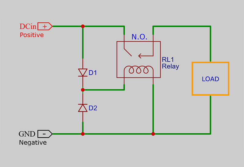
Reverse Polarity Protection with Relays:
The advantage of a relay is that it can handle extremely high current with almost no voltage drop across the
contacts.
Relays are maintenance-free and robust. They do not need a heat sink because they do not have any heating
problems.
The downside is that they take up a bit more space and are more expensive than diodes.
They constantly consume a current of between 20 and 40 ma. Therefore, they are not suitable for use in circuits
that are powered by a permanently connected battery. After a while, the relay will drain the battery.
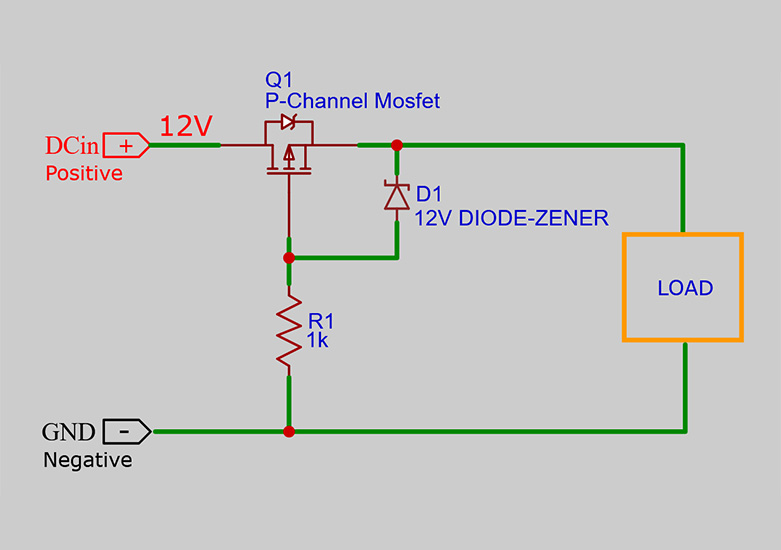
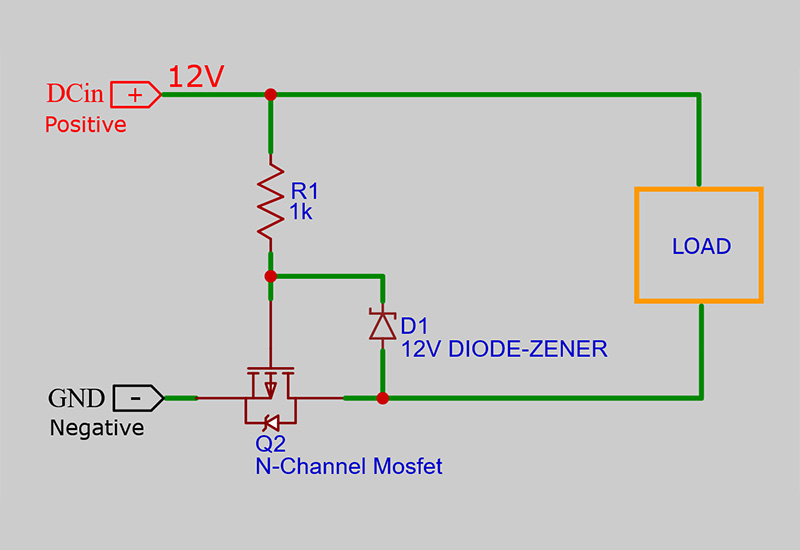
Reverse Polarity Protection with MOSFETs:
MOSFETs have a reverse diode that determines the voltage polarity, but a MOSFET conducts equally in both
directions when it is turned on.
Therefore, when the diode is forward biased and the MOSFET is on, the voltage across the MOSFET is determined
by Rdson and current, not by the forward voltage of the diode.
This useful feature has made MOSFETs preferred for reverse polarity protection circuits.
However, MOSFETs require some voltage between the gate and source to conduct. It should be noted that in a
very low voltage circuit (less than 5V), there may not be enough voltage to turn on the MOSFET.
When providing protection with a MOSFET, it may be preferable to have a low Rds resistance value. The lower this
resistance rating, the lower the power and heat loss of the circuit.
If we want to provide protection from the positive input of our circuit, we can use a P channel MOSFET, and if we
want to provide protection from the negative input, we can use an N channel MOSFET.