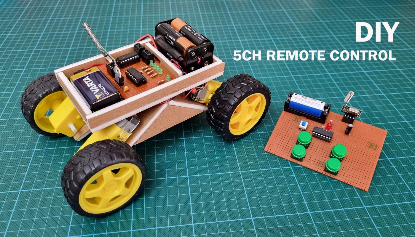
How to make 5 channels remote control for rc car & model vehicles. Diy remote control with TX2b & RX2B & Range Test.
This remote control circuit does not provide proportional command like RC systems. Commands work with on/off logic. That’s why they can’t control servo and ESC. In RC systems, one channel controls two functions (such as Forward-Backward). In this type of RF remote control, one channel provides only one function. This type of circuits can be preferred in simple structures as they are much cheaper than RC systems.
You needs:
TX-2B & RX-2B IC : https://s.click.aliexpress.com/e/_DefvZ8p
TX & RX Module: https://s.click.aliexpress.com/e/_DFekXlb
L293B IC: https://s.click.aliexpress.com/e/_DFekXlb
PCB Prototype board: https://s.click.aliexpress.com/e/_DBXKeHr
3mm & 5mm Leds: https://s.click.aliexpress.com/e/_DFekXlb
82R, 5x150R, 1K, 160K, 200K Resistors: https://s.click.aliexpress.com/e/_DmIcD2l
7805 Regulator IC 5V: https://s.click.aliexpress.com/e/_DF6iVRP
10uF 16V or 25V Capacitor: https://s.click.aliexpress.com/e/_DEspOZB
330nF capacitor: https://s.click.aliexpress.com/e/_DEvrpJJ
9V battery clip conector: https://s.click.aliexpress.com/e/_DEvrpJJ
JST 2 Pins connector & Cable: https://s.click.aliexpress.com/e/_DlMLxRf
PCB 2 Pins Mount Connector: https://s.click.aliexpress.com/e/_DlJ042Z
IC Connector Dip Socket (Dip14 & Dip16): https://s.click.aliexpress.com/e/_DEri1Yh
12×12 Micro button: https://s.click.aliexpress.com/e/_DlqlwWh
Switch Cap: https://s.click.aliexpress.com/e/_DlzJDQV
Self latching button: https://s.click.aliexpress.com/e/_DebAUVR
16340 Battery box: https://s.click.aliexpress.com/e/_DBYfFAl
DC 130 Gear Motor (TT Motor): https://s.click.aliexpress.com/e/_DDDEoYH
7.4V 450mAh LiPo battery: https://s.click.aliexpress.com/e/_DcRZOZr
4AA Battery Box: https://s.click.aliexpress.com/e/_De3Ib3P
80W soldering iron: https://s.click.aliexpress.com/e/_DD75tWX
Digital Multimetre AC DC A830L : https://s.click.aliexpress.com/e/_DmjzgOJ
Digital Multimetre AC DC ANENG XL830L : https://s.click.aliexpress.com/e/_DEJiyIP
UT61 Profesyonel Digital Multimetre Tester: https://s.click.aliexpress.com/e/_DmtkrmJ
Lipo Battery Charger: https://s.click.aliexpress.com/e/_DF5pqlz OR
https://s.click.aliexpress.com/e/_DlwNzmj OR
https://www.banggood.com/custlink/vKmdARTaK8
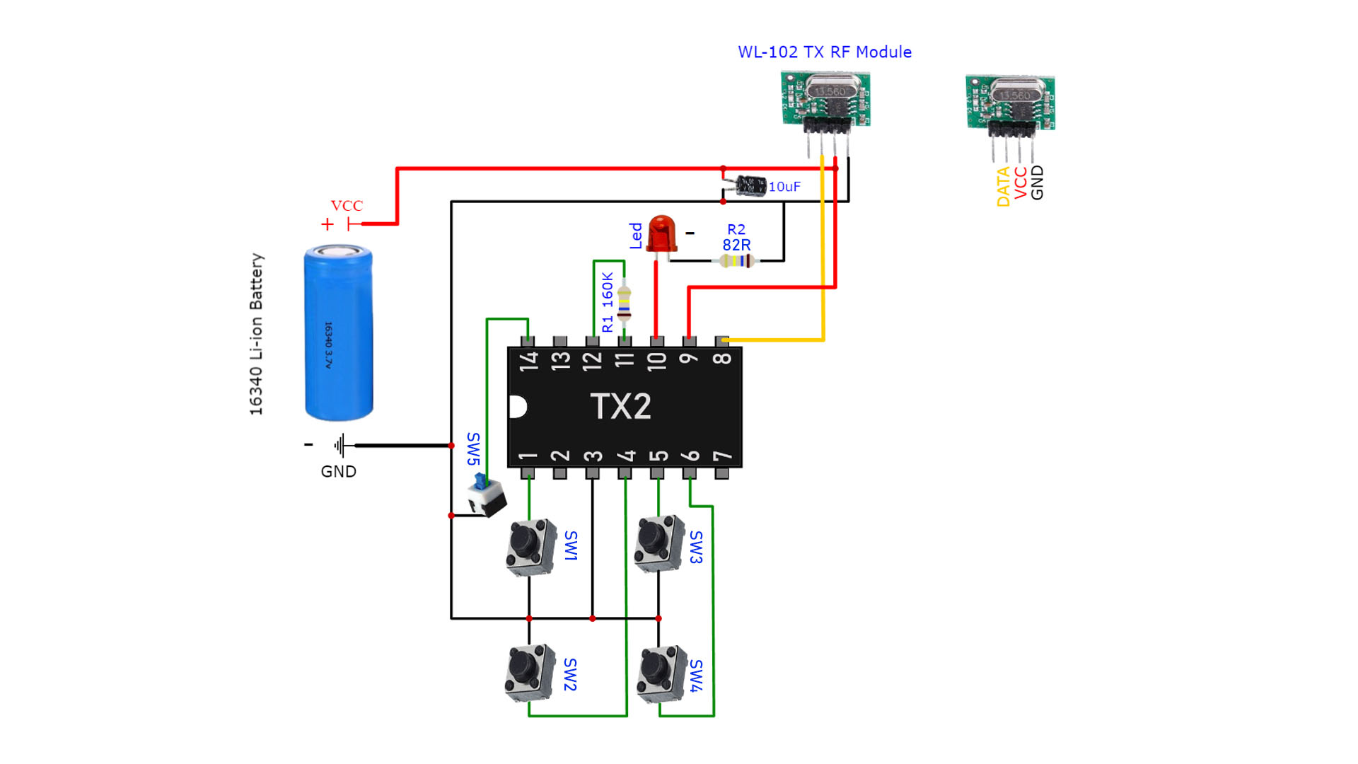
Transmitter Circuit:
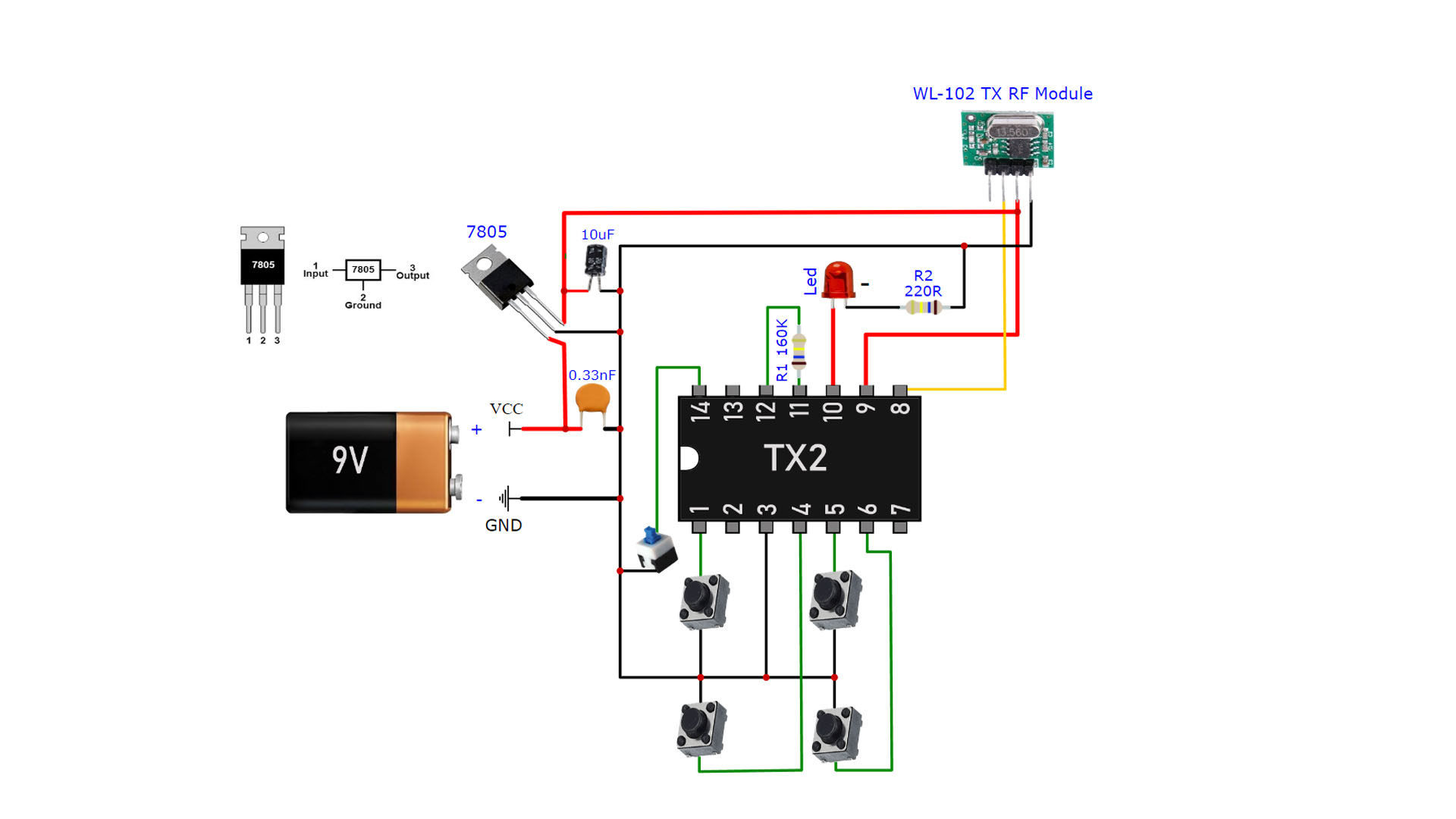
Optional Transmitter Circuit for 9V Battery:
If you prefer to feed the transmitter circuit with a 9V battery, a 7805 (5V) regulator should be added. Under normal conditions, the WL-102 transmitter module works with 3.6V. But it can work with 5V without any problem. If you want, you can also use the LD1117 (3.3V) regulator IC instead of the 7805. Pin connections of LD1117 are different from 7805. You should take this into account.
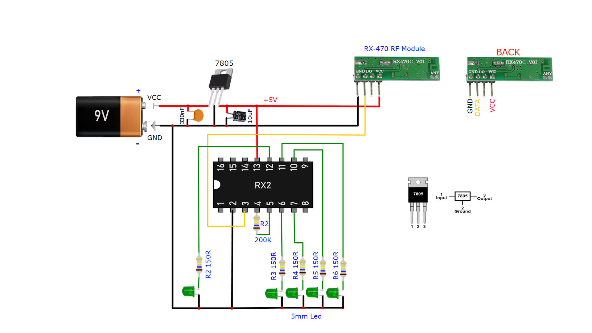
Receiver Circuit:
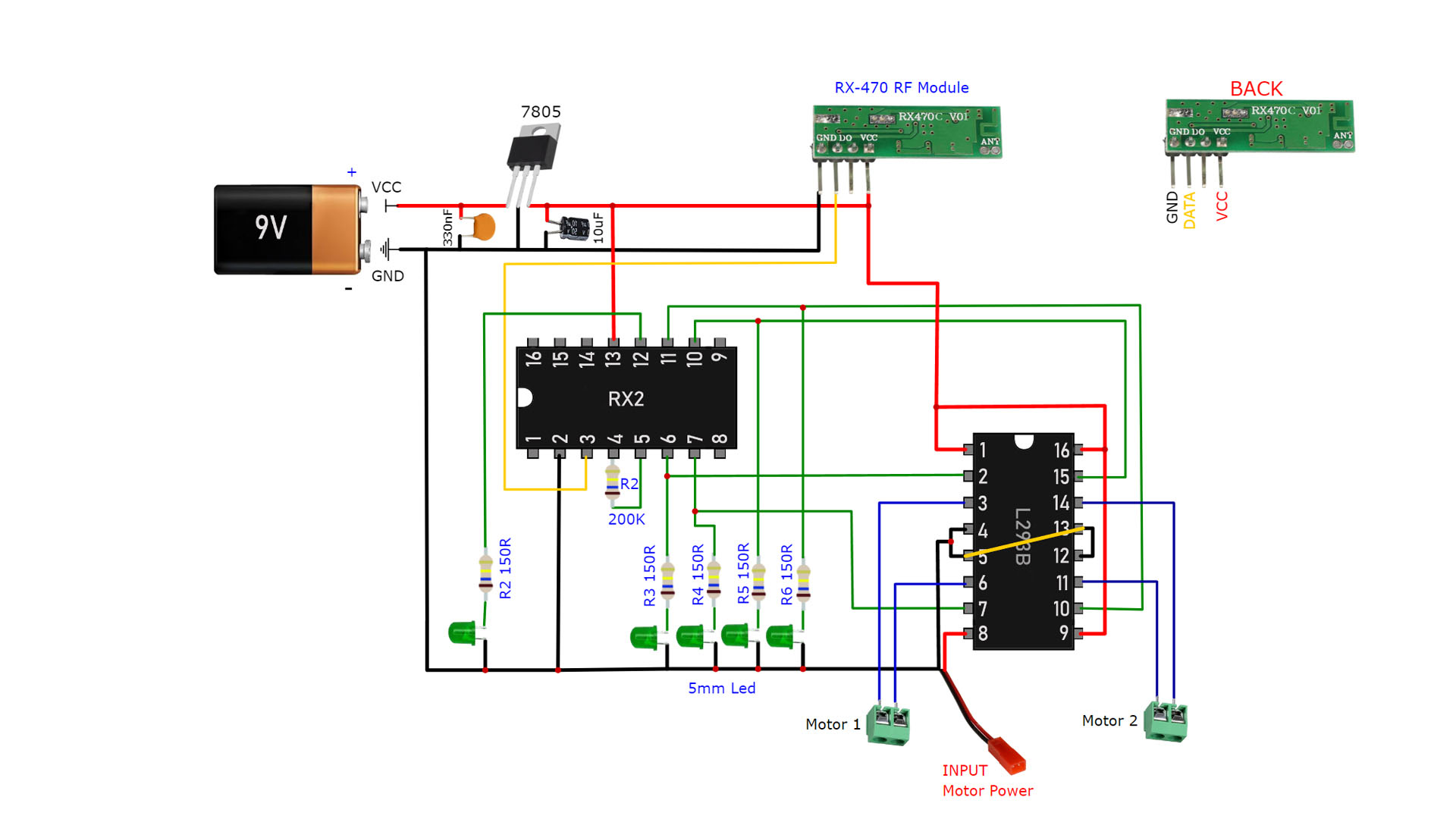
Receiver & L293B Motor Driver Circuit:
I used two separate batteries for the receiver circuit. A 9V battery powers the receiver circuit. The other feeds the motors. Different batteries can be used to power the motors. 4xAA battery, 7.4V (2S) LiPo or Li-ion battery etc.. L293B IC can work between 4-36V. You can feed external motor input up to 36V with different motor options. but the maximum current supported by each motor output is 1 amp. Motors that draw more than 1 amp should not be used. Otherwise, the L293B IC may be damaged.
Why didn’t I use one battery instead of two separate ones?
When the receiver circuit is powered by a single battery, the electrical noise of the motors can negatively affect the signal.

