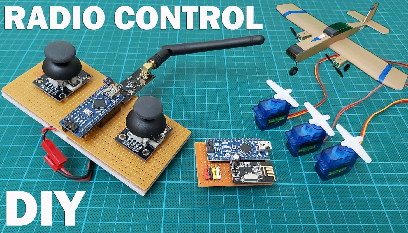
How to make a low cost 4 channel remote control for RC model aircraft, drone, cars and boats.
Construction of remote controls with proportional controls, which cost about 13-14 USD. It can be used for all kinds of model vehicle control such as model aircraft, drone, car, boat, tank.
Necessary materials:
2 x Arduino Nano
1 x NRF24L01 + PA Wireless Module
1 x NRF24L01 Wireless Module
2 x Arduino joystick
2 x 100uF Capacitor (16V or above)
1 x 13 * 6 cm PCB Board
1 x 5 * 3.5 cm PCB Board
Arduino Nano: https://www.banggood.com/custlink/vvGKUFyfT9
Arduino Nano & USB Cable: https://www.banggood.com/custlink/vDDGkGyA0y
Arduino Joystick: https://www.banggood.com/custlink/333mMmdABV
NRF24L01 Wireless Modul: https://www.banggood.com/custlink/KGvvMmEbnR
NRF24L01 + PA Wireless Modul: https://www.banggood.com/custlink/33GGqGhQbZ
PCB Boards:
https://www.banggood.com/custlink/v33vUGYsUd
https://www.banggood.com/custlink/3vGmz3yNqC
100uF Capacitor: https://www.banggood.com/custlink/DKDvMvyQUe
Headers:
https://www.banggood.com/custlink/m3vGqKdnfN
https://www.banggood.com/custlink/vG33zGYUmd
Other materials:
SG90 Servos: https://www.banggood.com/custlink/Kv3DS6stKo
20A ESC: https://www.banggood.com/custlink/mvvDggsH4C
7.4V 450Mah 2S LiPo: https://www.banggood.com/custlink/KKKGU3EqE3
DC 180 Motor 39000 RPM: https://amzn.to/35rD8Ar or bit.ly/2L62JqC
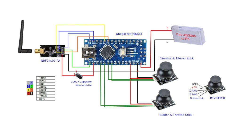
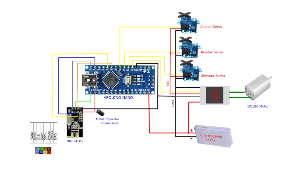
Transmitter Circuit & Receiver Circuit
If you do not have experience with Arduino and library files, you should watch the video below before uploading the code.
Transmitter Code
// 4 Channel Transmitter | 4 Kanal Verici

#include <SPI.h>
#include <nRF24L01.h>
#include <RF24.h>

const uint64_t pipeOut = 0xE9E8F0F0E1LL;   //IMPORTANT: The same as in the receiver 0xE9E8F0F0E1LL | Bu adres alıcı ile aynı olmalı
RF24 radio(7, 8); // select CE,CSN pin | CE ve CSN pinlerin seçimi

struct Signal {
byte throttle;
byte pitch;
byte roll;
byte yaw;
};

Signal data;

void ResetData()
{
data.throttle = 127; // Motor Stop (254/2=127)| Motor Kapalı (Signal lost position | sinyal kesildiğindeki pozisyon)
data.pitch = 127; // Center | Merkez (Signal lost position | sinyal kesildiğindeki pozisyon)
data.roll = 127; // Center | merkez (Signal lost position | sinyal kesildiğindeki pozisyon)
data.yaw = 127; // Center | merkez (Signal lost position | sinyal kesildiğindeki pozisyon)
}

void setup()
{
//Start everything up

radio.begin();
radio.openWritingPipe(pipeOut);
radio.stopListening(); //start the radio comunication for Transmitter | Verici olarak sinyal iletişimi başlatılıyor
ResetData();
}

// Joystick center and its borders | Joystick merkez ve sınırları

int mapJoystickValues(int val, int lower, int middle, int upper, bool reverse)
{
val = constrain(val, lower, upper);
if ( val < middle )
val = map(val, lower, middle, 0, 128);
else
val = map(val, middle, upper, 128, 255);
return ( reverse ? 255 - val : val );
}

void loop()
{
// Control Stick Calibration | Kumanda Kol Kalibrasyonları
// Setting may be required for the correct values of the control levers. | Kolların doğru değerleri için ayar gerekebilir.

data.throttle = mapJoystickValues( analogRead(A0), 524, 524, 1015, true );
data.roll = mapJoystickValues( analogRead(A1), 12, 524, 1020, true );      // "true" or "false" for servo direction | "true" veya "false" servo yönünü belirler
data.pitch = mapJoystickValues( analogRead(A2), 12, 524, 1020, true );     // "true" or "false" for servo direction | "true" veya "false" servo yönünü belirler
data.yaw = mapJoystickValues( analogRead(A3), 12, 524, 1020, true );       // "true" or "false" for servo direction | "true" veya "false" servo yönünü belirler

radio.write(&data, sizeof(Signal));
}
Receiver Code
//  4 Channel Receiver | 4 Kanal Alıcı
//  PWM output on pins D2, D3, D4, D5 (Çıkış pinleri)

#include <SPI.h>
#include <nRF24L01.h>
#include <RF24.h>
#include <Servo.h>

int ch_width_1 = 0;
int ch_width_2 = 0;
int ch_width_3 = 0;
int ch_width_4 = 0;

Servo ch1;
Servo ch2;
Servo ch3;
Servo ch4;

struct Signal {
byte throttle;
byte pitch;
byte roll;
byte yaw;
};

Signal data;

const uint64_t pipeIn = 0xE9E8F0F0E1LL;
RF24 radio(7, 8);

void ResetData()
{
// Define the inicial value of each data input. | Veri girişlerinin başlangıç değerleri
// The middle position for Potenciometers. (254/2=127) | Potansiyometreler için orta konum
data.throttle = 127; // Motor Stop | Motor Kapalı
data.pitch = 127;  // Center | Merkez
data.roll = 127;   // Center | Merkez
data.yaw = 127;   // Center | Merkez
}

void setup()
{
  //Set the pins for each PWM signal | Her bir PWM sinyal için pinler belirleniyor.
  ch1.attach(2);
  ch2.attach(3);
  ch3.attach(4);
  ch4.attach(5);

  //Configure the NRF24 module
  ResetData();
  radio.begin();
  radio.openReadingPipe(1,pipeIn);

  radio.startListening(); //start the radio comunication for receiver | Alıcı olarak sinyal iletişimi başlatılıyor
}

unsigned long lastRecvTime = 0;

void recvData()
{
while ( radio.available() ) {
radio.read(&data, sizeof(Signal));
lastRecvTime = millis();   // receive the data | data alınıyor
}
}

void loop()
{
recvData();
unsigned long now = millis();
if ( now - lastRecvTime > 1000 ) {
ResetData(); // Signal lost.. Reset data | Sinyal kayıpsa data resetleniyor
}

ch_width_1 = map(data.throttle, 0, 255, 1000, 2000);     // pin D2 (PWM signal)
ch_width_2 = map(data.pitch,    0, 255, 1000, 2000);     // pin D3 (PWM signal)
ch_width_3 = map(data.roll,     0, 255, 1000, 2000);     // pin D4 (PWM signal)
ch_width_4 = map(data.yaw,      0, 255, 1000, 2000);     // pin D5 (PWM signal)

// Write the PWM signal | PWM sinyaller çıkışlara gönderiliyor
ch1.writeMicroseconds(ch_width_1);
ch2.writeMicroseconds(ch_width_2);
ch3.writeMicroseconds(ch_width_3);
ch4.writeMicroseconds(ch_width_4);
}
Files with .h extension in the “include lines in the code are library files. Search for them with their names. Download it to your computer and copy it to the Arduino / Libraries folder. You must do this before uploading the code to the arduino).
Example: Necessary library link for NRF24L01: https://github.com/maniacbug/RF24 (Different version library files may be required depending on the Arduino board. It can be found by trying)

